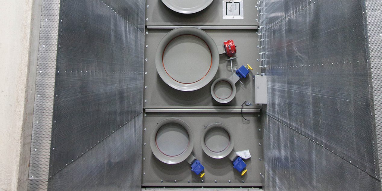
Dampers can have many different functions within an HVAC or process application. One such function prevents or restricts the free flow of air, requiring the use of an isolation damper. Isolation dampers are generally two-position dampers and actuated to be fully open or fully closed. The degree of isolation is largely determined by the application being isolated. An isolation damper, in its simplest form, may isolate a section of ductwork or a fan in an HVAC system. However, in an industrial process application, the degree of isolation can vary greatly.
Damper leakage can be defined by several different codes or standards. Codes and standards from third-party agencies such as Underwriters Laboratory (UL), the Air Movement and Control Association International, Inc., (AMCA) or the American Society of Mechanical Engineers (ASME) AG-1 are most typical, but not all that might be available. These codes define the air leakage rate downstream from the damper (through the damper blades). The codes may also define the amount of leakage allowed to escape the ductwork through the damper frame.
Damper blade leakage is the volume of air that can pass through the damper at a given pressure. This leakage is the air that passes through between the closed damper blades or between the blades and the damper frame. Damper blade leakage often is defined as a volume of air per the face area of the damper (cfm/sq ft or m3/s/m2 at a defined pressure). UL has leakage classes defined as Class I, II, or III (Figure 1), while AMCA has leakage classes defined as Class 1A, 1, 2, and 3 (Figure 2) or even “bubble tight.”
 |
| Figure 1 -- UL 555S (2014), Table 16.1 |
 |
| Figure 2 -- AMCA 511-10 (rev 2016), Table 5 |
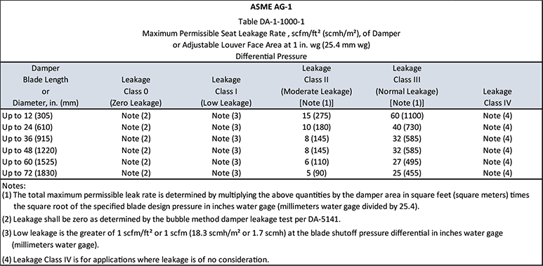
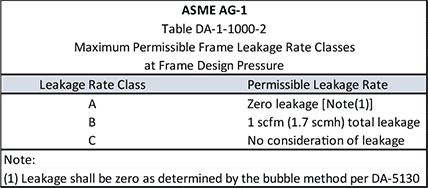
Bubble tight, Class 1 or 1A per ASME AG-1 (Figure #3 and #4) are the most typical requirements when discussing nuclear process isolation dampers. If the damper airstream being isolated contains contaminants--either small particulates or gasses that may be toxic--the damper might require a zero leakage or bubble tight rating to prevent any contaminants from passing through the damper. This rating might be needed to protect equipment or personnel downstream from being exposed to the contaminated airstream.
 |
| Figure 3 -- ASME AG-1 2015, Table DA-1-1000-1 |
 |
| Figure 4 -- ASME AG-1 2015, Table DA-1-1000-2 |
To meet zero, bubble tight or low leakage requirements for system isolation, the damper design should include blade and jamb seals. These seals often are made from various materials to meet other system requirements, such as temperature, pressure, and potential contaminants in the airstream.
Leakage through the damper frame may also be a consideration in addition to damper blade leakage. In these cases, codes like ASME AG-1 have established frame leakage classes that you can reference (See Figure 3). For example, the frame leakage class A may be required. This classification requires adding shaft seals to the damper design and its manufacturing.
Depending on the verification level the engineer may require for the damper performance, a damper may need to be tested to confirm these requirements are in place before shipment. This is true for all bubble-tight dampers where damper performance can vary based on the quality of the manufacturing processes used to build the damper. In other cases, prototype testing or published performance might be sufficient justification.
Isolation dampers have uses in many different applications and can be defined by many different codes or standards. Specifying engineers should be aware of these codes and how to specify the leakage requirements needed for the system design.


from