Laboratory Exhaust Fans Controls
It is important for controls on laboratory system to operate correctly, not only from a life safety aspect but also from energy savings and equipment life. Greenheck Vektor laboratory exhaust systems have a variety of levels in controls options. The system controls range from those that manage the all the components on the Vektor exhaust system to others that adjust discharge nozzles maintaining velocities with maximized plume heights and those that simply integrate and communicate with another control system operating on a building management system.
Controls logic and operable components are developed together as complete systems for seamless integration and coordination into lab applications.
OVERVIEW
Vektor System Control
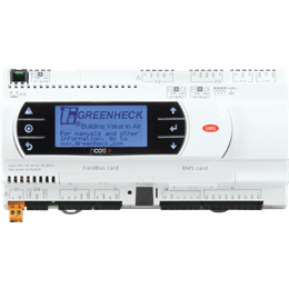
The Vektor System Control (VSC) package offers a pre-engineered, stand-alone controller for laboratory exhaust fans. Components and sequences of operation easily integrate Greenheck Vektor exhaust fans into a variable or constant volume lab exhaust system.
Duct pressure modulation, fan speed, redundancy and fan rotation, isolation damper and bypass damper control are all handled by the Vektor System Control.
This control system is suitable for the following options and configurations:
Duct pressure modulation, fan speed, redundancy and fan rotation, isolation damper and bypass damper control are all handled by the Vektor System Control.
This control system is suitable for the following options and configurations:
- Vektor models H, MH, MD, CH, CD
- Single or dual fan configurations (maximum of two fans & isolation dampers)
- Exhaust system redundancy options of N+1, N-1 or none
- Single or dual bypass air damper applications
- BACnet® IP and BACnet MS/TP supported communication protocols
Variable Geometry Nozzle
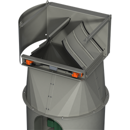
The Variable Geometry Nozzle (VGN) automatically adjusts to maintain the specified discharge velocity as lab airflow varies. This safely prevents re-entrainment in the make-up air unit and provides energy savings through lower fan speeds in reduced lab flow situations without introducing bypass air to maintain outlet velocities.
The VGN controller receives a signal from the factory provided pressure transducer and converts that signal into a fan flow. It then calculates the appropriate nozzle opening and sends a signal to the nozzle to adjust it to the proper size opening to maintain desired nozzle outlet velocity. Feedback signal provides BMS details as fan flow, nozzle position and a system alarm. The VGN controller does not signal operation of the fan speed, isolation or bypass dampers and it does not control duct pressure; those parameters are controlled by the BMS.
This control system is suitable for the following options and configurations:
- Vektor models MS, CS
- Controller for one or more fans (maximum of four)
- Adjusts individual fan outlet area to maintain discharge velocity
- Outlet velocity is a read/write parameter allowing on the fly adjustments based on outside parameters such as wind speed, chemical concentration levels or laboratory air flows.
- Communication with BMS through analog connections
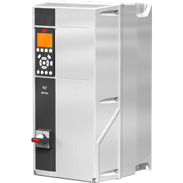
Variable Frequency Drive
Stand-alone VFDs supplied with Vektor fans. Sized and factory programmed with supplied motor information along with maximum speed per the supplied motor and fan construction.
System control signal and operation of the fan speed, as well as other systems components such as isolation and bypass damper(s), is done via the BMS.
VFD features:
System control signal and operation of the fan speed, as well as other systems components such as isolation and bypass damper(s), is done via the BMS.
VFD features:
- NEMA 1 (indoor) or NEMA 3R (outdoor) rated enclosures
- BACnet® IP, BACnet MS/TP and MODBUS RTU are all supported communication
- Integrated display
- 24 VDC power supply